Troubles with Spiders
The latest Element14 video is to create some Halloween effects.
I modified a smoke machine to be activated by a microcontroller and that allowed me to trigger it based on motion. As mentioned in the last post, the controlling software was MicroPython. But it wasn’t all smooth progress.
I also tried a different modification to the smoke machine e.g. adding a hose to its output. I had a 3D printed connector which glued to the front of the machine with a screw thread to attach a regular vacuum cleaner hose. This seemed to work brilliantly but then stopped completely. MarkP on Mastodon had also tried this and clarified that the problem is to do with the smoke condensing on the tube. So that idea was rolled back.
Another challenge was the need to create the footprints for some of the components. This includes some push to fit connectors and the relay. I made a silly mistake on the relay in that the position of the contacts was reversed. As as the relay was asymmetrical that meant it didn’t fit. So the solution was to mount that on the back of the board. Had that kind of issue before so should have spotted it.
I am in two minds about the push for connectors. Initially, I thought these only supported one use so once the cable was in, that was it. But ok further examination it does appear that you can push the top of the connector to release the cable. I didn’t have a chance to test this so not sure if that works well or not.
The original design used a second opto-isolator to trigger the relay. When tested this didn’t work. I’m guessing not enough current through the transistor portion of the isolator. A TIP31 transistor could be fitted into existing holes and a resistor was tacked on the back.
I also missed a few components from the board, a resistor for the inbound sensing, a miss wired power line (4.5v rather than 3.3v) and missed off the level shifter and power circuit for the motion sensor. These last components were added on a separate board using an AdaFruit power boost circuit. I might just create some boards with both these parts, the power boost and the level shift. As I think that could prove useful in future.
One of the 3D prints was also a challenge to print. It was a holder for the main printed circuit board. I added some angled braces to give the board better support. But that meant I had to use supports when printing. It came out a bit ugly but seems to have worked ok. I think in future it would be better to print this kind of structure in two parts that slot together. Then bot could be printed flat without support, improving reliability and print speed.
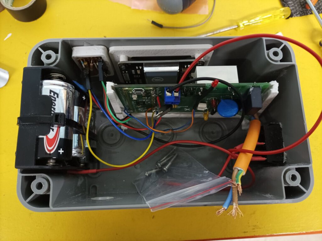
Other enhancements would be to have an LED triggered with the relay to help with diagnostics. I had to do that “by ear, listening for the clicks”. And I think a second output LED which could be triggered when the pulses representing the mains voltage were detected. That would allow a low voltage equivalent of the remote control to be created. I wonder if it would also be possible to house some of the components in the main smoke machine housing meaning that only low voltages were present in the main box.
I had bought some conformal coating to cover up the solder connections which is UV cured. But give the number of modification to the board, I didn’t have chance to use this. I still think that was a good idea as it would give the end user one more protection from the circuit.
I don’t always have time to explain all these issues in the video but I think it is important to share the things that went wrong as well as the success.
 Posted in: Electronics
Tags: 3d Printing, pcb
Posted in: Electronics
Tags: 3d Printing, pcb




 Metal sculpture in brass, mounted on an 1800s French Coin